Calibration Method For Detection Deviation Of Positioner
The detection deviation of the dynamic four-wheel locator is large, and it can be calibrated and adjusted from the equipment’s own calibration, installation and debugging, as well as external environment and vehicle factors to restore accuracy. The specific methods are as follows: Equipment calibration 1. Calibrate the sensor Check the accuracy of the sensor: Use professional calibration tools, such as standard measuring blocks or calibration fixtures, to check the accuracy of the sensor. Connect the sensor with the calibration tool according to the specified way, and observe whether the output value of the sensor is consistent with the standard value. If there is any deviation, it can be adjusted or re-calibrated according to the equipment manual. Clean and maintain the sensor: regularly clean the dust, oil and debris on the surface of the sensor to prevent it from affecting the transmission and reception of signals. For optical sensors, pay special attention to cleaning the lens to ensure smooth transmission of light. For contact sensors, check whether the probe is worn, and replace it in time if it is worn. 2. Measurement system calibration Zero point calibration: After the device is turned on, perform zero point calibration according to the requirements of the operation manual. Usually, the vehicle is parked on a horizontal lifting platform, so that the wheels are in a natural state, and then the device software is operated to zero the measurement values of the various sensors to eliminate the initial error of the system. Angle calibration: Calibrate the measurement Angle of the four-wheel locator using a standard Angle calibration instrument. The calibrator is mounted on the wheel, and in conjunction with the sensor, the equipment parameters are adjusted so that the measured Angle value is consistent with the standard Angle value of the calibrator. Length calibration: For four-wheel aligners using laser or ultrasonic measurement of wheel base, wheelbase and other length parameters, it is necessary to use a standard length calibration rod for calibration. Place the calibration rod in the specified position, and the length measured by the device should be consistent with the actual length of the calibration rod. Otherwise, it needs to be adjusted. Installation and commissioning 1. Check the installation position Lift level check: Use a level to check the levelness of the lift to ensure that the lift is level in all directions. If the lifting platform is not level, it will cause the vehicle to be tilted during the detection, affecting the measurement results. The lifting platform can be levelled by adjusting its support feet or hydraulic system. Sensor installation check: Check whether the sensor is firmly installed on the wheel and whether the position is correct. The sensor should be perpendicular to the center plane of the wheel, and the installation Angle should meet the requirements of the device. The mounting bolt should be tightened to prevent the sensor from displacing during detection. 2. Set device parameters Vehicle parameter input: According to the actual model, frame number, tire specifications and other information of the vehicle to be detected, accurately input into the software system of the four-wheel locator. The four-wheel positioning parameters of different models are different, and the correct input of vehicle parameters is the basis to ensure the accuracy of detection results. Measurement mode selection: According to the type of vehicle and detection needs, select the appropriate measurement mode. For example, for ordinary cars and commercial vehicles, their measurement patterns and parameter standards may be different. Some devices also have measurement modes for different suspension system types, which should be selected according to the actual situation. Environmental and vehicle factors check 1. Check the environment Site flatness: Ensure that the ground of the test site is smooth and there is no obvious uneven or slope. Uneven site will cause the vehicle to produce additional tilt and displacement during detection, affecting the measurement accuracy. If the site is not level, the ground can be repaired or other level site can be selected for testing. Light and electromagnetic environment: The test site should avoid direct light and strong electromagnetic interference. Strong light may interfere with the work of the optical sensor, and strong electromagnetic signals may affect the communication between the sensor and the device. You can take shading measures or adjust the device position to avoid strong light and electromagnetic interference sources. 2. Vehicle status check Tire status: Check whether the pressure of the tire meets the standard, whether the tire wear is uniform, and whether the tire surface is damaged. Insufficient or excessive tire pressure will deform the tire and affect the positioning parameters of the wheel. Uneven tire wear can cause the wheel to jitter when turning, making the measurement data inaccurate. The tire pressure should be adjusted to the standard value, and the tires with serious wear or damage should be replaced in time. Chassis component inspection: Check whether the suspension system, steering system, ball and other components of the vehicle chassis are loose, deformed or damaged. The failure of these components can cause changes in the positioning parameters of the wheel. If the chassis parts are found to have problems, they should be repaired or replaced in time, and then four-wheel positioning detection.
Free shipping on orders over $50!
- Satisfaction Guaranteed
- No Hassle Refunds
- Secure Payments
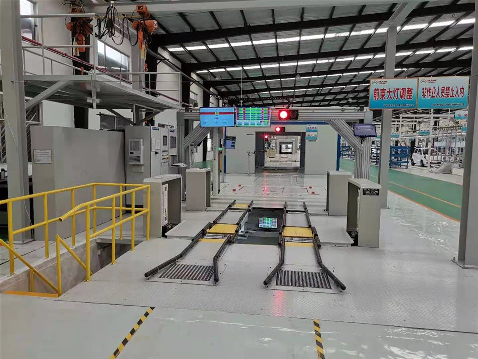
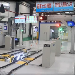
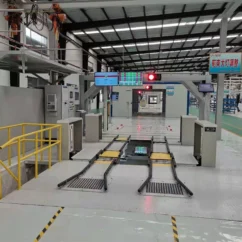
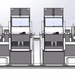
The non-contact four-wheel positioning instrument is a special device used to measure and adjust the wheel positioning of the assembled vehicle. Through the positioning instrument, the four-wheel positioning of the vehicle is located and measured/judged to ensure that the wheel positioning meets the design parameters and requirements.
Wheel weight, toe in and camber of wheels, inspection of main pin camber, camber, thrust angle, and maximum steering angle, calibration of toe in and camber, automatic collection and calibration of wrench torque to a specified database, and optional wheel arch inspection function.
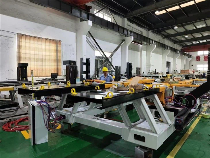
Innovative advantages: Exclusive invention patents leading the world, side cameras added to the front wheels and targets added to the rear wheels, automatic calibration of the zero point value of the rear wheel sensors after changing the wheelbase, eliminating initial errors and ensuring accurate measurement results.
Exclusive innovative wheelbase adjustment mechanism ensures that the wheel rotation center coincides with the drum group rotation center, accurately measuring the maximum steering angle.
Test content:
Front wheel front bundle (left/right), front wheel total front bundle, rear wheel front bundle, front wheel out (left/right), kingpin back tilt, kingpin inward tilt, rear wheel out (left/right), maximum steering Angle, etc. The device can be measured repeatedly by static/dynamic measurement and adjustment, the front bundle and roll out of the wheel, the display in the control cabinet, the display above the front of the car and the operator’s display in the pit to display the measurement value in real time.
Kingpin back tilt Angle, kingpin inner tilt Angle measurement method: random inspection.
Measuring range (accuracy calibrated with static calibration stand):
| Item | Test range | Precision | Repeat accuracy | Remark |
| Front pulley | ±10° | ±1′ | ±0.2′ | 100% detection |
| Wheel roll out | ±10° | ±2′ | ±0.4′ | 100% detection |
| Thrust Angle | ±10° | ±2′ | – | 100% detection |
| Steering wheel Angle | ±10° | ±0.5′ | ±0.5° | 100% detection |
| Kingpin tilted inward | measuring range±20° | – | <±4° | 100% detection |
| Kingpin leans back | measuring range±20° | – | ±0.1° | 100% detection |
| Maximum steering Angle | ±45° | ±0.1° | ±0.1° |


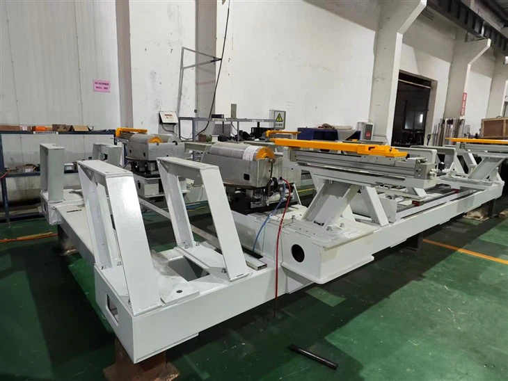
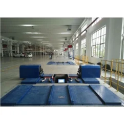
The non-contact dynamic four-wheel positioning instrument adopts the non-contact German visicon laser measurement system and the imaging processing technology of line laser irradiation, which has the characteristics of high measurement accuracy, small repeatability error and stable operation.
The proper axial position of a vehicle’s tires is essential for ensuring safe and smooth driving. To achieve this, our company has developed advanced equipment for detecting the axial position of tires, which boasts outstanding technical features and stable performance.
This equipment is based on high-precision sensors and cutting-edge image recognition technology that can swiftly and accurately detect the wheel’s position. The sensors are placed at the center of the wheel hub, and as the wheel rotates, they collect data on its position. Additionally, the image recognition system analyzes the tire rotation to determine the tire’s displacement.
One of the significant advantages of this equipment is its accuracy. It can determine the axial position of the tire within a range of 0.01 mm, ensuring that each tire is precisely aligned. This accuracy is essential because any misalignment can cause uneven tire wear and negatively impact the vehicle’s performance and safety.
Moreover, our equipment is incredibly versatile and can be used to test vehicles of different sizes, ranging from small passenger cars to large commercial trucks. With our device, accuracy, and speed, we can determine the axial position of each vehicle’s tires within a matter of minutes.
In summary, the advanced equipment we have developed for detecting a vehicle’s tire position is an essential tool for ensuring safe and smooth driving. Its technical features, high accuracy, and speed make it highly reliable and efficient. Choosing our equipment means choosing the best for your vehicle.
Hot Tags: calibration method for detection deviation of positioner, China calibration method for detection deviation of positioner manufacturers, suppliers, factory, Load Brake Tester, Axle Load Tester, Vehicle Drying Room, Steering Wheel Test Stand, High end Inspection Line, Automotive High end Inspection Line


Reviews
There are no reviews yet.